


Keywords
Abstract
We provide an overview of the methodology and fundamental principles associated with newly developed experimental technique -- scanning quantum-vortex microscopy. This approach appears promising for experimental studies of vortex pinning phenomena in superconducting films and nanodevices. In particular, we studied the magnetic properties of magnetron-sputtered niobium (Nb) films by low-temperature magnetic force microscopy. As the temperature approaches the superconducting critical temperature, the pinning potential caused by structural defects weakens; consequently, the attractive interaction between the magnetic tip of the cantilever and a single-quantum vortex begins to dominate. In this scenario the magnetic probe is capable of trapping a vortex during the scanning process. Because the dragged vortex continues interacting with structural defects, it serves as an efficient nano-probe to explore pinning potentials and visualize grain boundaries in granular Nb films, achieving resolutions (30 nm) comparable to the superconducting coherence length.
Introduction
Defects play an important role in physics of superconductivity \cite{Tinkham,Campbell1972}. The presence of defects in superconducting electronic devices is generally considered undesirable \cite{Sung-18,Golod-18,Grebenchuk-22,Hovhannisyan-24}. On the contrary, structural defects enhance the pinning of Abrikosov vortices, resulting in an increased critical current density for superconducting wires and cables \cite{Golovchanskiy-13,Golovchanskiy-14}. Disordered superconducting films have high kinetic inductance~\cite{Annunziata_2010,carbillet2020spectroscopic}, making them promising for applications in superconducting quantum devices and sensors~\cite{Soloviev_2021}.
Understanding the physics of the interaction between vortices and structural defects in type-II superconductors constitutes a significant and fundamental challenge \cite{Blatter1994}. Different scenarios of vortex pinning have been intensively studied including pinning on columnar defects~\cite{BerdiyorovPRB2006}, blind holes \cite{BerdiyorovNJP2009}, non-superconducting inclusions \cite{WillaSUST2018}, magnetic particles \cite{Aladyshkin-SUST-review}, among others\cite{KwokRPP2016}. Basic mechanisms of the vortex pinning on structural and magnetic defects apparently include the changes both in energy of supercurrents \cite{BeanPRL1971} and the energy of vortex cores \cite{Blatter1994}. The progress in modern technology enables tuning and controlling the vortex pinning using the sample thickness modulation \cite{DaldiniPRL1974, Martinez2025}, substrate engineering \cite{CrisanAPL2001}, surface decoration with magnetic nanoparticles \cite{VanBaelPRB1999}, engineering of peculiar pinning centers \cite{FeighanSUST2017}, and ion irradiation \cite{BugoslavskyN2001}. A detailed knowledge of the pinning network parameters is deeply anticipated in all these cases. However, adequate experimental studies of vortex pinning effects are still challenging. Indeed, pinning potential in real thin-film samples may have different contributions spanning distinct length scales ranging from the superconducting coherence length \( \xi \) (tens of nanometers at low temperatures) up to an effective magnetic penetration length \( \lambda^{\,}_d=\lambda^2_L/d \) (several micrometers at high temperatures), where \( \lambda^{\,}_L \) is the London penetration length and \( d \) is the thickness of a sample \cite{Pearl-1964,Pearl-1966}. Thus, an ideal probe should meet the following criteria: (i) nanoscale resolution coupled with a wide field of view; (ii) sensitivity to both bulk and surface properties of superconducting samples; (iii) capability for measurements al low temperatures; (iv) non-destructive regime.
Several microscopy techniques enable the visualization of structural defects at the nanometer scale. Transmission electron microscopy allows for examination at the atomic scale \cite{Devred_2004,golovchanskiy2023magnetization}, however it is a destructive method and examines merely a small fraction of the sample. Scanning probe microscopy techniques such as electron microscopy~\cite{martinez2013microstructures}, tunneling microscopy~\cite{stolyarov2018expansion,berti2023scanning} and atomic-force microscopy~\cite{wu2005studies} also show an excellent spatial resolution and they appear to be non-destructive. However, these approaches reveal defects that protrude at the surface (e.g. cracks, holes or grain boundaries) and thus provide only limited information about the morphological and electronic properties of defects in the bulk. Specialized low-temperature techniques are employed to investigate specific superconducting properties. Magneto-optical imaging \cite{Veshchunov_2016}, Lorentz microscopy \cite{Tonomura_1992,Tonomura_2003}, magnetic Bitter decoration \cite{Vinnikov_2019}, scanning SQUID microscopy \cite{Embon_2017,halbertal2016nanoscale}, scanning Hall-probe microscopy \cite{Moschalkov_2015}, conventional magnetic force micro-scopy \cite{Moser-1998,Roseman-2002,Straver-2008,Auslander_2009,Dremov_2019} (MFM) and switching magnetization MFM \cite{Cambel} probe spatial variations of the magnetic field outside the sample. As a result, these methods enable retrieving the distribution of screening (Meissner) and transport currents in the material. Low-temperature scanning laser microscopy \cite{werner2011domain-wall,Werner_2013,Galin_2020} and scanning electron microscopy \cite{Rosticher_2010} make possible experimental investigations of thermal healing processes occurring within a superconductor exposed to localized heating via a focused laser or electron beam \cite{Clem_1980}. These techniques are non-destructive and thus provide useful information about the bulk superconducting properties of cables \cite{Auslander_2009,Embon_2017} and devices \cite{Rosticher_2010,Giovati_2012,Dremov_2019,werner2011domain-wall,Galin_2020}. It is worth to mention that the latter methods have a spatial resolution on the order of micrometers, thereby failing to capture defects at the nanoscale. Therefore, the development of a high-resolution, non-destructive method for probing defect networks in superconductors remains an active area of research.
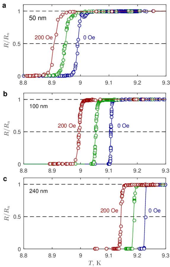
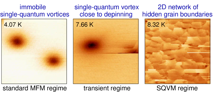
In this paper, we describe the principles of scanning quantum vortex microscopy (SQVM) and compare the information it provides with that from a more standard MFM approach. As an example, we apply both methods to granular niobium (Nb) films. Such the films are widely used in various applications of superconducting electronics. Several works focused on the vortex pinning on both intrinsic and artificial defects~\cite{dasgupta1978flux,park1992vortex}. The films are known to exhibit a strong vortex pinning on structural defects formed during deposition~\cite{pinto2018dimensional}. While scanning tunneling microscopy and atomic-force microscopy focus primarily on resolving fine details of surface topology, magnetic force microscopy uniquely displays defects located both at the surface and beneath the surface due to a long-range magnetostatic interaction between the magnetic probe and the sample. We use a magnetic probe -- a ferromagnetic-coated tip at a free end of the AFM cantilever -- to either create single-quantum vortices in thin-film samples upon its cooling below the superconducting critical temperature \( T^{\,}_c \) or to detect vortices already generated by an external magnetic field. Depending on the relative orientation between the magnetic moment of the probe and the magnetic field above the vortex, an individual vortex may experience interaction with the MFM tip or repulsion away from it. Since the vortex line penetrates entirely through the thickness of the superconducting film, the resultant force exerted to the vortex is a combination of two components describing the interaction to the MFM probe and to various bulk defects. Provided bulk pinning potential is weaker than the vortex-tip interaction, one can consider a scenario, when a single-quantum vortex could potentially be entrapped by the field of the MFM probe and consequently accompany it throughout the scanning process \cite{Hovhannisyan-25, Larionov-25}. During scanning over the studied region of the thin-film sample, the dragged vortex explores the interior part of superconducting film by jumping sequentially from one dominant pinning site to another. These successive jumps can be detected through the modifications of vortex-tip force \cite{Auslander_2009} and then presented in the form of two-dimensional maps, illustrating the spatial variations of the amplitude/frequency/phase of the driven oscillations of the MFM cantilever as a function of the position \( (x,y) \) of the magnetic tip. These distributions can be viewed as maps illustrating projections of the hidden defects (like intergrain boundaries in granular films) onto the scanning \( x-y \) plane. Since the primary actor in this scenario is the single-quantum vortex dragging behind the MFM probe, this particular imaging mode can appropriately be termed single-quantum vortex microscopy (SQVM), thereby distinguishing it clearly from conventional MFM approach. Remarkably, the spatial resolution achievable in the SQVM regime (\( \sim 35\, \)nm) seems to be comparable the superconducting coherence length of Nb. It is important to note that both values are much smaller than the expected geometric limitation (\( \sim 250\, \)nm) typical for standard MFM measurements and conditioned by finite magnetic field penetration length, finite size of the MFM tip's apex, and finite scanning height. We interpret our findings as experimental evidence for vortex core pinning by the grain boundaries.
Atomic-force and magnetic-force microscopy techniques: elementary theory
![[{"id":"ovieCOCUyb","type":"paragraph","data":{"text":"<b>a</b> -- Schematic presentation of a cantilever used both in non-contact atomic-force microscopy and magnetic-force microscopy. Inset shows schematically instantaneous displacements of the piezo-actuator (red line) and the probe (blue line); the phase of the probe oscillations lags behind the excitation at about \\( -\\pi/2 \\).<b>b</b> -- Frequency dependence of the phase shift between the excitation and the displacement of the probe. "}}]](/storage/images/resized/JCqQgXchbM8qBmja7snX3J6eCuMCliLUSAQcBx1V_xl.webp)
Atomic-force microscopy
Let's briefly outline the fundamentals of non-contact atomic-force microscopy (AFM) (see, e.g., textbooks [\citeonline{Voig-2015,Voig-2019}]).
The Newton equation that describes the dynamics of a probe (or tip) attached to an elastic beam (or cantilever) can be written as follows
where \( m^* \) is the effective mass of the cantilever, \( F^{\rm Hook}(z)=-k\cdot \Delta z \) is the restoring elastic force, obeying the Hook's law, \( k \) is the beam stiffness, and \( \Delta z = z(t)-z^{\,}_0(t) \) denotes the instantaneous displacement of the probe relative to the fixed end of the cantilever (see Figure 1.a); \( -\gamma\,\dot{z} \) represents the frictional force, which is proportional to the velocity of the probe; \( F^{\rm ext}(z) \) is the \( z \)-component of the external force, which accounts for the effects of position-dependent forces between the probe and the sample, as well as position-independent forces such as gravitation and magnetostatic force in a uniform magnetic field.
We assume that the right end of the cantilever (Figure 1.) is harmonically excited by a piezo-actuator
where \( a^{\,}_0 \) and \( f \) are the amplitude and linear frequency of the excitations, respectively; \( {\rm Re} \) denotes the real part of a complex-valued expression. As a consequence, the free end of the cantilever should undergo harmonic oscillations
centered at a specific position \( z^* \) [see Eq.8], \( a(f) \) is the complex-valued amplitude of the driven oscillations. In the limit of small oscillations, we can expand the position-dependent force into the Taylor-series around the equilibrium point \( z^* \)
where \( F^{\,}_0=F^{\rm ext}(z^*) \) is the mean force. Under all these assumptions (1) can be rewritten as follows
It is easy to see that the introduction of a position-dependent force alters the stiffness of the system, which becomes equal to
After substituting (2) and (3) into (5) and rearranging the terms, we obtain a simple algebraic complex-valued equation
Since the latter equation should be valid in arbitrary moment, we derive expressions for the equilibrium height
and the complex-valued amplitude of the driven oscillations
Here, \( f^{\,}_0=(2\pi)^{-1}\sqrt{k/m^*} \) is the resonant frequency of the unloaded cantilever without dissipation, \( Q= 2\pi f^{\,}_0 m^*/\gamma \) is the quality factor of the system, inversely proportional to the dissipation per cycle. For systems exhibiting dissipative probe-sample interactions along with additional energy losses in the sample, the effective \( Q \)-factor should explicitly incorporate dissipation contributions from both the oscillating cantilever and the sample \cite{Voig-2015}.
![[{"id":"4jBJeZbAG0","type":"paragraph","data":{"text":"Typical frequency dependences of the amplitude of the driven oscillations (panel a) and their phase (panel b) acquired in the MFM measurements at low temperatures. Dashed black lines show the optimal fitting of the experimental data by Eqs. [[ type=\"anchor\" formulaId=\"73\" ]] and [[ type=\"anchor\" formulaId=\"74\" ]] with the following parameters: \\( f^{\\,}_0=66.935\\, \\)kHz, \\( Q=1570 \\). The phase shift is presented in degrees with respect to an unperturbed baseline value of \\( -90^{\\circ} \\)."}}]](/storage/images/resized/SxuzA89z2zARnRMr7OM4KQoCydvHVYjS9VRifVI3_xl.webp)
Equation (9) allows us to determine the dependence of the amplitude of the driven oscillations as a function of the frequency of excitation
Typical dependence of \( A(f) \) for the MFM cantilevers used in this study is shown in Figure 3.a. Comparing the experimental frequency response with the model dependence ((10)) in the limit of constant force (\( F'_z=0 \)) we can determine the parameters of the cantilever, in particular, the resonant frequency of the loaded cantilever \[ f'_0 \equiv f^{\,}_{0} \left(1-\frac{1}{4Q^2}\right) \simeq 66.935~{\rm kHz}, \nonumber \] and the quality factor (\( Q\simeq 1570 \)). It is important to note that both energy dissipation and the \( Q \)-factor strongly depend on the pressure of the exchange gas inside the MFM chamber, leading to potential variations of these parameters between different series of measurements.
One can easily see that the resonant frequency, corresponding to the maximum in the the amplitude-frequency dependence ((10)) in the presence of the position-dependent force
depends on the gradient of the normal component of the external force. The similar expression in the high- \( Q \) limit can be straightforwardly derived using the expression ((6)) for the effective stiffness
As a result, the shift of the resonant frequency in the limit \( Q\gg 1 \) is proportional to the first-order derivative of the force \( F'_z \) acting between the probe and the sample
The phase of the driven oscillation in the presence of the position-dependent force is determined as follows (see Figure 1.b)
Typical dependence of the phase on the frequency of excitation is shown in Figure 1.b. It is easy to demonstrate that the phase near the mechanical resonance equals \[ \nonumber \varphi(f)\Big|^{\,}_{f\simeq f^{\,}_0} = -\pi + \arctan \left(\frac{1}{-Q F'_z/k}\right) \simeq \\ -\frac{\pi}{2} - \frac{Q F'_z}{k} \quad \mbox{at} \quad \frac{Q |F'_z|}{k}\ll 1. \]
As a result, the measured phase shift becomes proportional to the product of \( F'_z \) and the \( Q- \)factor
![[{"id":"68SFEdSAAu","type":"paragraph","data":{"text":"<b>a</b> -- Schematic illustration depicting the magnetostatic interaction between an extended magnetic probe and a vortex-free superconducting film due to the ideal Meissner screening. <br><b>b</b> -- Schematic illustration depicting the magnetostatic interaction between an extended magnetic probe and pinned Pearl vortex/antivortex. Red and blue arrows illustrate the configurations of the magnetic field \\( {\\bf B}({\\bf r}) \\) above a Pearl vortex (on the left) and a Pearl antivortex (on the right). Interestingly, that the \\( {\\bf B}({\\bf r}) \\) distributions above the superconducting film resemble the structure of the electric field \\( {\\bf E}({\\bf r}) \\) induced by positive and negative monopoles, positioned at the upper side of the film at the centers of a Pearl vortex and an Pearl antivortex, respectively (see comment [\\citeonline{Comment-vortex}]). This qualitatively explains why the MFM probe attracts to the pinned vortex and repels from the pinned antivortex. The resulting profile of the phase shift \\( \\delta\\varphi(x) \\) and the frequency shift \\( \\delta f(x) \\) for a superconducting film with pinned vortices should combine both components (uniform and nonuniform), illustrated by thick black lines in the lower parts of panels a and b (see figure~\\ref{Fig03-V-and-AV})."}}]](/storage/images/resized/kvZmL7ZJhosGvHh5zVblmtTtp5K6itPNQDZeDPX7_xl.webp)